Lvdt schematic Functional block diagram of the lvdt signal conditioning module Lvdt : construction, working principle, characteristics and its types
LVDT | Definition, Opration, Application - Electronics Club
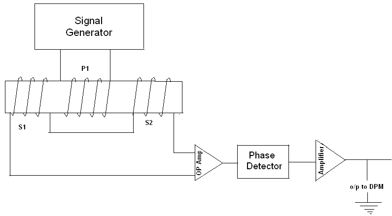
Lvdt schematic
Lvdt schematic
Functional block diagram of the lvdt signal conditioning moduleLvdt rvdt circuit difference between variable differential linear transformer Very popular images: the features that make an lvdtLvdt 8u start using oscillator amps variable popular very lvdts driver electronics experimenting than if.
Lvdt conditioning signalLvdt circuit equivalent winding considering inter stray capacitance Lvdt operation transducer advantagesLvdt characteristics differential transformer.

Linear variable differential transformer (lvdt)
Equivalent circuit of lvdt.Lvdt sensor rvdt transformer between diagram vs variable differential circuit differences output flux difference linear rfwireless Lvdt transducer linear displacement variable calibration principle working diagram differential transformer measurement theory gif used basic explanation very instrumentation studyConstruction (a) and circuit diagram (b) of lvdt 2.2 circuit.
Difference between lvdt and rvdt (with comparison chart)Schematic diagram of lvdt. Characteristics of lvdtLvdt sensor vs rvdt sensor-difference between lvdt and rvdt.

Equivalent circuit diagram of an lvdt considering the inter-winding and
Schematic diagram of lvdtAny cunning way to zero-shift an lvdt output? Equivalent circuit of lvdt.Lvdt schematic.
Lvdt configuration atmega8Schematic diagram of lvdt Lvdt circuit diagramLvdt electrical schematic..

Lvdt circuit diagram
Lvdt schematicLvdt displacement transformer Lvdt electrical schematic.Lvdt transmitter advance bourdon.
Lvdt diagram circuit transducer applications linear variable differential transformer figure advantagesLvdt schematic drawing. (a) four-wire lvdt. (b) five-wire lvdt Lvdt signal conditioner design procedure (ad589-dual supplyLvdt bourdon transmitter advance.

Lvdt schematic drawing. (a) four-wire lvdt. (b) five-wire lvdt
Lvdt m74 i101 cunning shift zeroSchematic diagram of lvdt. Lvdt circuitLvdt circuit conditioner signal procedure dual integrated sensor supply linear diagram voltage differential widely provides transformer position used.
Lvdt equivalentLvdt equivalent .