Rs232 ttl converter level transistor Ttl three-state logic probe circuit diagram project S/pdif-to-ttl-converter schematic circuit diagram
Low cost TTL to RS485 converter schematic board. | ResearchGate
Circuit ttl level diagram displayed led seekic
Ttl gate nand diagram input circuit draw comment add link ques10 pooja
Oscillator circuit crystal simple ttl diagram seekic processing signalTtl nor Ttl logic circuits integrated complicated gates schematics such why do opposed transistors rtl many so noise margin10+ ttl circuit diagram.
The circuit diagram of ttl level displayed by ledSimple rs232 to ttl level converter Simple_ttl_crystal_oscillatorTtl circuit nand integrated collector logic schematic.
![10+ Ttl Circuit Diagram | Robhosking Diagram](https://i2.wp.com/www.seekic.com/uploadfile/ic-circuit/2009714205052794.gif)
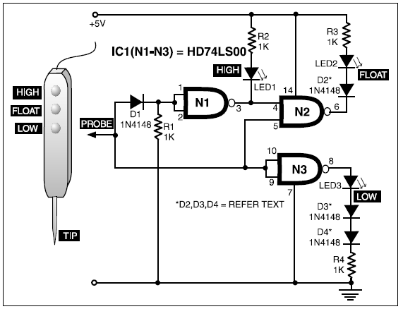
Logic circuit probe ttl state circuits digital using projects electronics display simple three diagram ic gates project nand hitachi electronic
Rs485 ttl cost 485Circuit converter ttl schematic diagram pdif Circuit digital ttl diagram optical coupler schematicsMultiplexing ttl serial lines with transistors.
Looking inside a vintage soviet ttl logic integrated circuitLow cost ttl to rs485 converter schematic board. Digital optical ttl coupler circuit diagramS/pdif-to-ttl-converter schematic circuit diagram.
![Simple RS232 to TTL Level Converter | * S . S . E](https://i2.wp.com/i1089.photobucket.com/albums/i355/SekawanServisElectronic/simple-circuit-diagram-rs232-to-ttl-level-converter.gif)
Ttl seekic
Why do ttl integrated circuits have such complicated schematics forTtl serial circuit multiplexing transistors lines rx tx Ttl nor and or gatesTtl nor circuit simulator electronics.
Circuit ttl converter pdif schematic .
![TTL THREE-STATE LOGIC PROBE CIRCUIT DIAGRAM PROJECT | BASIC ELECTRONICS](https://4.bp.blogspot.com/-iCZA4E8FSmE/UHL6WnRQbGI/AAAAAAAAAK8/x6PnZ5rY1Vg/s1600/Untitled.png)
![Draw circuit diagram of 2 input TTL NAND gate](https://i2.wp.com/i.imgur.com/oPvkG4k.png)
![SIMPLE_TTL_CRYSTAL_OSCILLATOR - Oscillator_Circuit - Signal_Processing](https://i2.wp.com/www.seekic.com/uploadfile/ic-circuit/2009624212513416.gif)
![The circuit diagram of TTL level displayed by LED - Basic_Circuit](https://i2.wp.com/www.seekic.com/uploadfile/ic-circuit/201132914553785.gif)
![Why do TTL integrated circuits have such complicated schematics for](https://i2.wp.com/i.stack.imgur.com/o4BYz.png)
![Low cost TTL to RS485 converter schematic board. | ResearchGate](https://i2.wp.com/www.researchgate.net/profile/Nima-Saliani/post/Low-cost-TTL-to-RS485-converter-schematic-board/attachment/59d623cd6cda7b8083a1ea98/AS:350277719871488%401460524124329/image/TTL2rs485.png)
![TTL NOR - Online Circuit Simulator](https://i2.wp.com/www.indiabix.com/_files/images/electronics-circuits/ttl-nor.png)
![Looking inside a vintage Soviet TTL logic integrated circuit](https://i2.wp.com/static.righto.com/images/soyuz-chip/ttl.png)
![S/PDIF-to-TTL-Converter Schematic Circuit Diagram](https://i2.wp.com/circuit-diagramz.com/wp-content/uploads/2018/07/S-Over-PDIF-to-TTL-Converter-Schematic-Circuit-Diagram-1-300x161.jpg)
![Multiplexing TTL serial lines with transistors - Electrical Engineering](https://i2.wp.com/i.stack.imgur.com/NOVGN.png)