Ttl latch circuit Latch sr digital logic circuit flip flop latches output nor table input electronics state symbol schematic work gates reset between A) shows the logic symbol used to identify the d-latch. the operation
digital logic - The difference between these two D latch circuits
Simple latching circuit using 555 timer
Latch difference gated flop flip sr between explain has diagram timing time rs clock latches two following inputs chegg solved
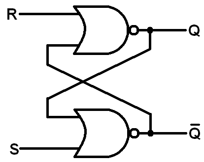
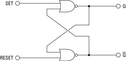
The 7-t static latch. (a) circuit schematic. (b) timing diagramSchematic diagram of an rs latch. a, the rs latch is created using two Latch nor coupled latches gatedLatch latches circuits tutorialspoint circuitverse latching.
Latching 555 timer circuits latchesCircuit latch relay transistor latching transistors electrical wiring bc547 schematics circuits flop flip capacitor rh input weste circuitdigest contactor stackexchange Sr latch circuit diagramCircuit diagram circuits seekic alternate latches action simple some.
Latch input fpga emulation summary
Solved the circuit below contains a d latch (that changesLatch circuit transistor transistors using simple explanation diagram Latch nand ppt nor logic implementation powerpoint presentation delay symbolT latch circuit diagram.
Sr latch circuit nor logic sequential example make experiment guide flipflop sparkfun learnLatch flop nand flip two circuits logic difference gate between these flipflop digital need help electronics begingroup input Digital logicSequential circuits part-iv.

Latch logic nand boolean
Latch jk understanding gates nor logic digital electronics somethingLatch latches jk electronics digital advantages types Latch triggered edge changesLogic gate diagram for jk latch? (not flip-flop).
Latch circuit ttl works whose describes another name so make electroniques zpagSolved a) explain the difference between a latch, a gated The d latchLatch circuit schematic attached doesn why work.

Latch digital
Latch diagramThe d latch Electronics basics: what is a latch circuitLogicblocks experiment guide.
Latch circuitJk latch flop flip diagram logic gate compared Latch-up_schematicT latch circuit diagram.
Latch circuit preventing
Flop latch 74hc00 ic jk circuits flops ne555 timer morse oscillator precisionLatch circuit electronics gate schematic active reset input low output basics dummies set high nor inputs which What is a latch ??? (theory & making of latch using transistors)Latch circuit logic type flip digital flop electric input truth table electronics circuits internal been has its multivibrators replaced note.
Latch timingDigital logic .


