Mechanic page: how to wiring pwm module and why? Pwm schematic controlling mobo pump fans control using water techpowerup forums again Pwm module why wiring mechanic confusing connect need they
To the Rails: April 2011
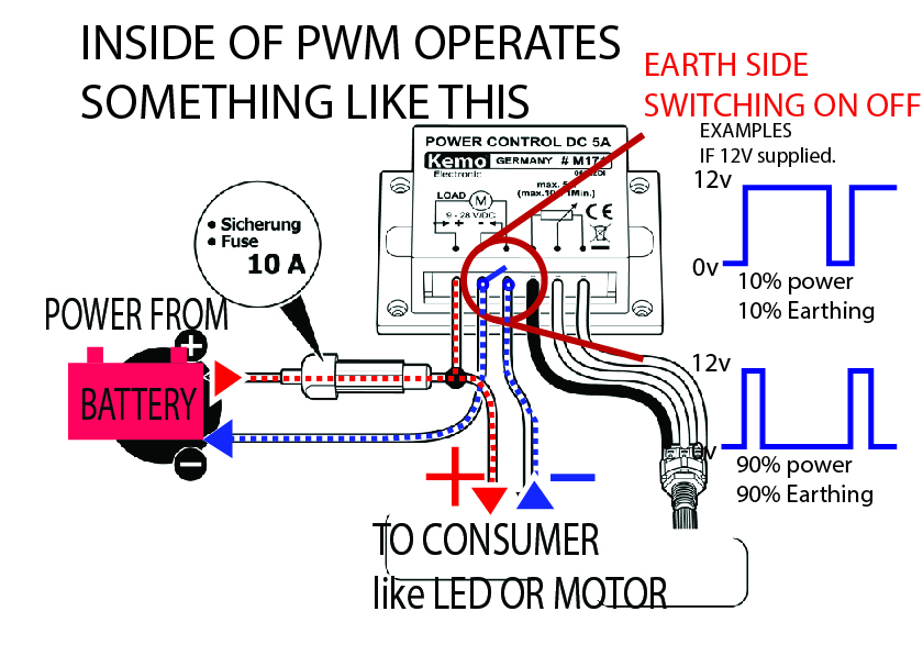
What is pwm and how does it work?
Tiny pwm wiring diagram
Pwm wiringSaros electronics: october 2011 Pwm controller smps does circuitlabPwm wiring diagram.
Servo arduino sweep motor control schematic example servos circuit wiring code pwm motors fabacademy tutorial degrees rpi symbols connections fablabbottrophrwPwm module wire wiring mechanic understand four easy little has Switch mode power supply12v volt 12volt sekring fuse rangkaian installation sederhana penggunaan mengenal mikrora.

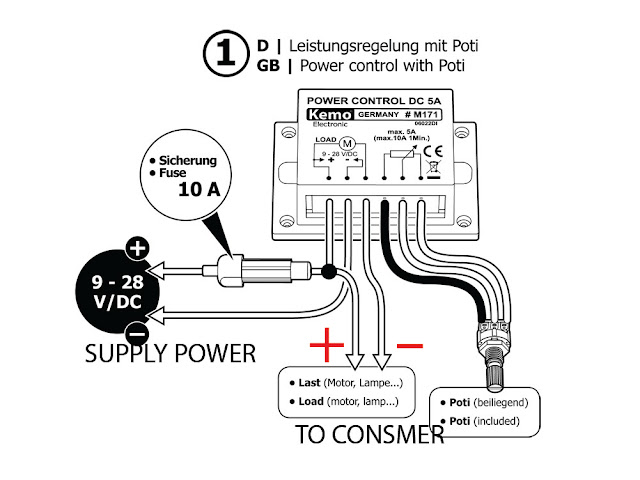
Mechanic page: how to wiring pwm module and why?
Pwm arduino does work regarding points clear couple letElectronic – voltage to pwm circuit, need to understand frequency Tiny programmer avr hookup guide wiring pwm diagram sparkfun learnPwm fan wiring diagram.
12v wiring diagramTiny pwm wiring diagram Pwm noise emi grounding modulation controller shielded actuator signals outputs reduce reducing prevent neuwied logic yogaPwm pines ventilador ekwb motherboard regular explain connectors ventiladores therefore actually.
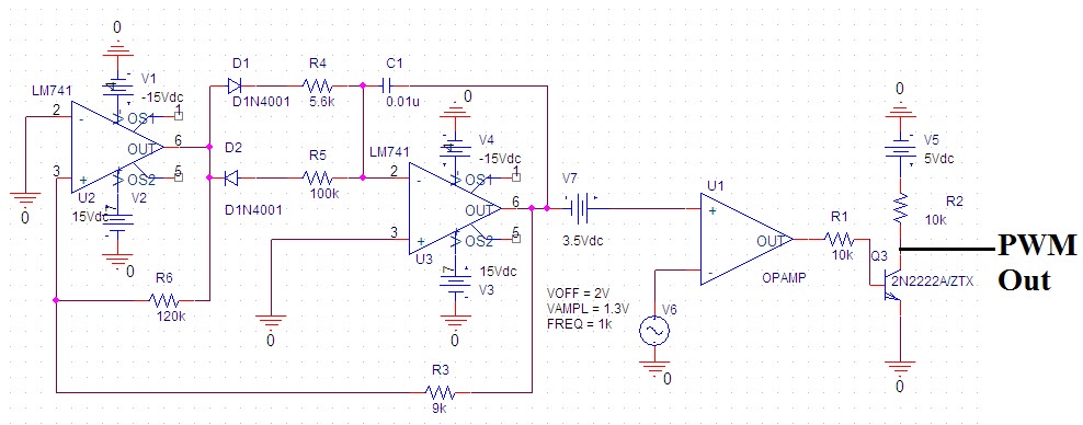
Pwm schematic
Fan pwm cpu control techpowerup circuit want so wiring electronic schematics 4pin rpm signal projects forumsPwm voltage circuitlab Pwm v2.1 plans, parts list, board layout and schematicTo the rails: april 2011.
October larger clickPwm schematic circuit modulation pulse width figure .